Rotating Biochamber Manufacturing Project
APPL 310 – BME Design & Manufacturing II
This project was intended to introduce several basic and modern manufacturing technologies in common use in (biomedical) engineering companies. The focus was placed on the manufacturing processes themselves, so the design for the acrylic pieces and SolidWorks part were provided by the instructor. All groups were comprised of 3 students.
Final Assembly Drawing
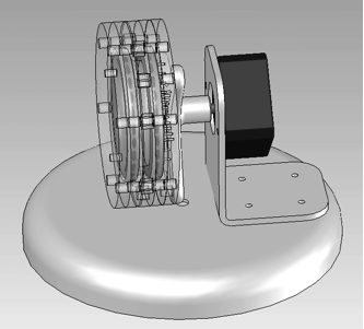
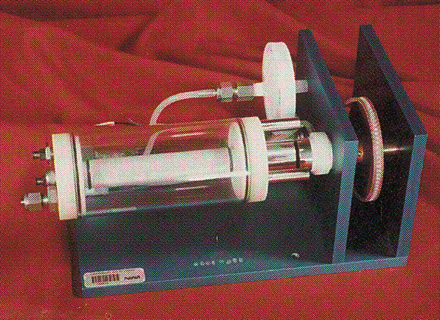
The final assembly drawing (left) was based on a commercial product (right).
 |
 |
Biochamber Assembly
The biochamber was assembled from 5 circular plates of acrylic sheet (polymethyl methacrylate or PMMA), shown below. These plates were manufactured using a laser cutter from solid cast acrylic sheet. The two spacer rings were solvent welded to the main ring nut capture after the small o-rings and stainless steel hex nuts were installed.
Note that each of these components has an outer diameter of 3.5”, and has a “bolt circle” (3.000”), which is a ring of evenly spaced holes. The holes can be either circular, or in this case, some are hexagonal to hold machine nuts in place during assembly. Although the bolt circle is designed for even spacing of 12 holes, 3 of these are omitted from each piece because they are not required for the assembly.
The biochamber can be disassembled for cleaning, so six bolts holes are used to hold the chamber together and to create the seal internally against the two internal orange silicone o-rings. The three remaining holes are for attachment of the motor flange.
| 1. FACE PLATE |  |
- Material: clear cast acrylic, 0.236” thick sheet - Quantity: 1 per assembly - Post processing: tap the two inner holes ¼” – 28 TPI Luer fittings screwed into the ¼”-28 holes to permit fluids and cells to be injected or removed using a syringe. |
| 2. BASE PLATE |  |
- Material: clear cast acrylic, 0.236” thick sheet - Quantity: 1 per assembly - Post processing: ensure loose material cleared from small holes Plate functions to allow gas exchange across a membrane. A circular piece of Saran film should be placed over the small holes before final assembly |
| 3. MAIN RING NUT-CAPTURE |  |
- Material: clear cast acrylic, 0.236” thick sheet - Quantity: 1 per assembly - Post processing: 1- Align holes and weld to one spacer ring with dichloromethane 2- Install into each hex a single # 006 o-ring sandwiched between Two 18-8 stainless steel hex nuts (#6-32 small pattern hex nut) |
| 4/5. SPACER RINGS |  |
- Material: clear cast acrylic, 0.177” thick sheet - **Note thinner acrylic** - Quantity: 2 per assembly - Post processing: Align and weld to main ring nut capture Welding of the spacer rings was done with dichloromethane solvent (in a well-ventilated area). |
The nut capture ring and stainless steel nuts were used because this is far superior to attempting to tap threads into acrylic sheet. The nuts are inexpensive (about 2.5 cents each) and provide strong metal threads to allow tightening of the bolts to assure a reliable fluid seal. Tapped threads in plastic are in general time-consuming (and therefore costly) to make, and are relatively weak and prone to failure under repeated tightenings.
The biochamber assembly also requires one sheet of Saran Wrap, cut by hand to a circular diameter of 2.70 to 2.75 inches, and additional hardware. The Saran film acts as the semi-permeable gas membrane to cover the array of small holes on the base plate. It needs to seal on the inside of the bioreactor, between the base plate and the large orange silicone o-ring.
Additional Parts
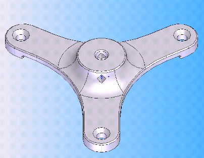 |
Motor Flange The motor flange for this project was built using the FDM polycarbonate machine at UNC (right). The motor flange allows the biochamber to mount directly to the motor shaft. Post processing/Final machining: The center hole was slightly undersized to ensure a good fit. Post-printing, the center hole was drilled with a .196” diameter drill (wire gage size #9 drill). |
|
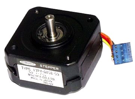
Motor Stepper Motor Description: - Minebea Astrosyn - 17PY-Q202-03 Stepper Motor - BIPOLAR STEPPER 5 Volt, 0.4 Amp, 12.5 Ohms. 0.9°/step, 400 steps/rev, 12.5 Ohm coils. NEMA17 size. |
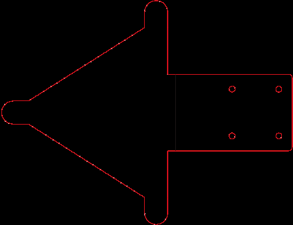 |
Base The shape shown to the left was cut from a single piece of acrylic sheet on the laser cutter. It required four bends (each is a forming operation) to complete the geometry. Bending was done with a heated strip bender at each of the three tabs at the corners of the triangle piece and at the line in the middle of the sketch. |