YOCLK
Two YOCLKs (your own clock) were constructed to produce waveforms of different frequencies. Both circuits included astable multivibrators and are intended to operate with Vs+ = 5V. An LED was used to visually demonstrate the function of the CLK.
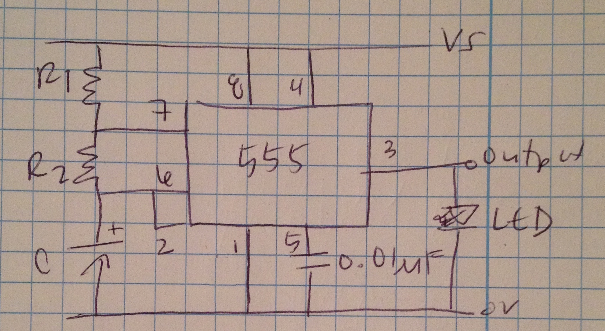 Cirucit Diagram
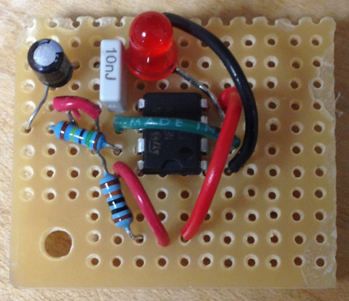
The first YOCLK was constructed to operate at a frequency of 5Hz. R1 was a 100kΩ resistor, R2 was a 1.5MΩ resistor, and C1 was a 0.1µF electrolytic capacitor. Additionally, a 0.1µF capacitor was connected to pin 5 which was subsequently connected to ground to reduce noise, and pin 4 was connected to Vs +. Once the components were soldered onto the circuit board, the circuit had a frequency of 4.386Hz and a duty cycle of 51.32%.
YOCLK in Action:
 |
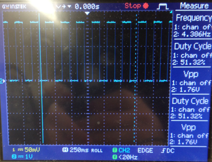 |
| Soldered Circuit Board | Output Displayed on Oscilloscope |
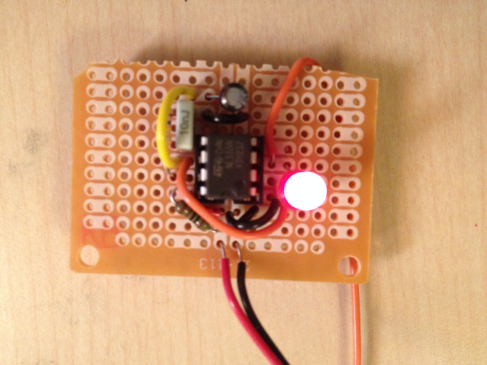
The second YOCLK was constructed to operate at a frequency of ~1.18Hz. R1 was a1kΩ resistor, R2 was a 150kΩ resistor, and C1 was a4.7µF electrolytic capacitor. Additionally, a 0.1µF capacitor was connected to pin 5 which was subsequently connected to ground to reduce noise, and pin 4 was connected to Vs +. Once the components were soldered onto the circuit board, the circuit had a frequency of 1.179Hz and a duty cycle of 52.60%.
Updated YOCLK in Action:
 |
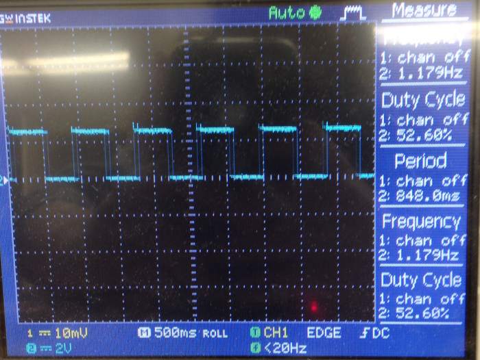 |
| Updated Soldered Circuit Board | Updated Output Displayed on Oscilloscope |