Adaptive RPM Control System
PHYS 352 – Electronics II
Designed system including H-bridge controlled DC motor with notched-wheel attachment and optical detector. Used pulse width modulation to operate H-Bridge and modify motor speed. Developed adaptive LabVIEW system to adjust pulse width and force DC motor to match user-specified desired RPM using feedback from optical detector.
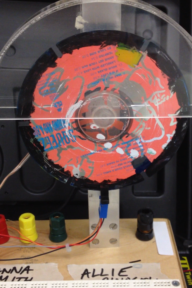
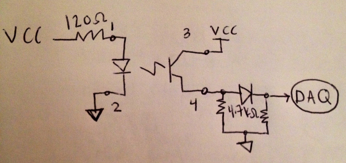
Dan’s Wheel is a chopper CD wheel mounted on a small electric motor (Figure 1). The edge of the wheel passes through an optical detector consisting of an infrared LED and a phototransistor (Figure 2). The small notches on the wheel allow light to enter the detector. The first part of this lab required constructing an H-Bridge circuit to drive the bi-directional motor (Figure 3). This H-Bridge contains an extra transistor to allow control of the speed using the duty cycle of the signal entering this transistor. Next, a program called Motor.vi was developed in LabVIEW. This program could be used to start and stop the motor, change the direction of the motor, and set the angular speed to a desired value of revolutions per minute (RPM). Finally, the VI was altered to allow the user to specify the desired end location of a specific slit (3, 6, 9, and 12 o’clock).
 |
 |
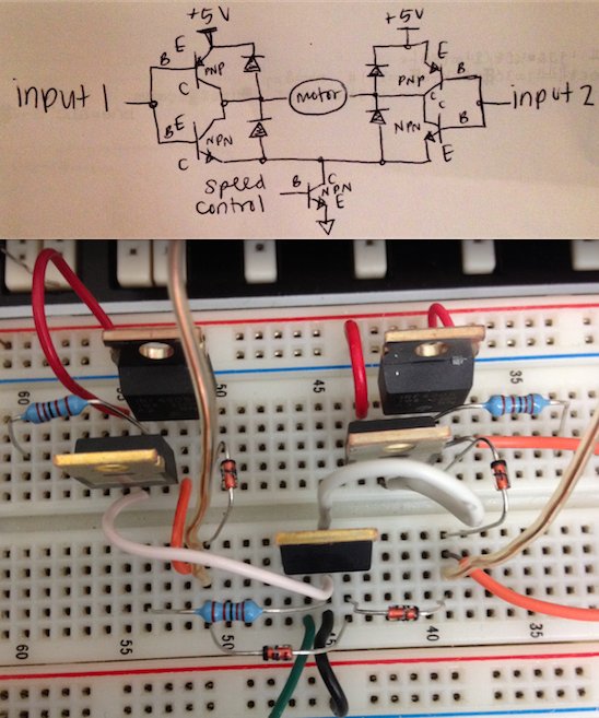 |
| Figure 1: Dan’s Wheel | Figure 2: Detector Circuit | Figure 3: H-Bridge Circuit with Pulse Width Modulation |
MotorControl.VI
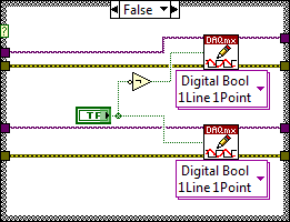
This VI uses four input lines via the NI USB-6008 data acquisition device (DAQ). Two of these control the direction of a motor via an H-Bridge circuit, one controls the speed of the motor using pulse width modulation, and the final reads the output of the sensor to allow the user to determine the speed of a rotating wheel. (See Lab 9 for a more detailed description). When the START button is pressed, the user may select a desired direction of the wheel as well as a desired set point frequency in RPM. The program runs the wheel with these specifications. The line which reads the output of the sensor is filtered so that only values over 1V are considered “HIGH”. The voltages from this line are read and displayed on the front panel. The frequency is detected from this line using a single tone detect VI. Once the output is detected as high, the frequency is divided by 10 (to convert the 6-slitted wheel from Hz to RPM). This value is then divided by the desired RPM and inverted. The error is determined by 1 minus this difference * 100. Both the detected RPM and RPM Error are displayed on the front panel. Then the desired RPM is divided by 10 and multiplied by this ratio to get the duty cycle. The wheel cannot operate at values under 25 or over 100, so values outside of this range are changed to these limits. The duty cycle is then sent to a square wave which runs from 0 to 5V at a frequency of 100 Hz. This output determines the speed of the wheel.

Front Panel

Block Diagram
 |
 |
 |
| False Condition of RPM Conditional Loop | False Condition of DAQmx Write Conditional Loop | Icon |